Project - Family Sign
This is one of the first real, non-test projects I created with my CNC.
Tools and Software used
- Fusion 360
- Inkscape
- V carve bit
- DW660 cutout tool
- Mill bit (I’ve just been using the Rotozip sabrecut ones made for the cutout tool - they work well enough and are super cheap)
- Laser module
- MPCNC Machine with GRBL controller
Files
Design Process
Create a Design in Fusion 360
Create a shape sketch in Fusion 360. I use Fusion 360 because it’s easier to get exact dimensions there than in graphics oriented tools like Inkscape. It also allows for parametric shapes so you can reuse the drawing and alter the dimensions to fit the wood you are working with.
Be sure to use millimeters for the sketch dimensions (you can still enter sizes in inches if you want, but the exported file must be in mm).
- First I create a shape like this:
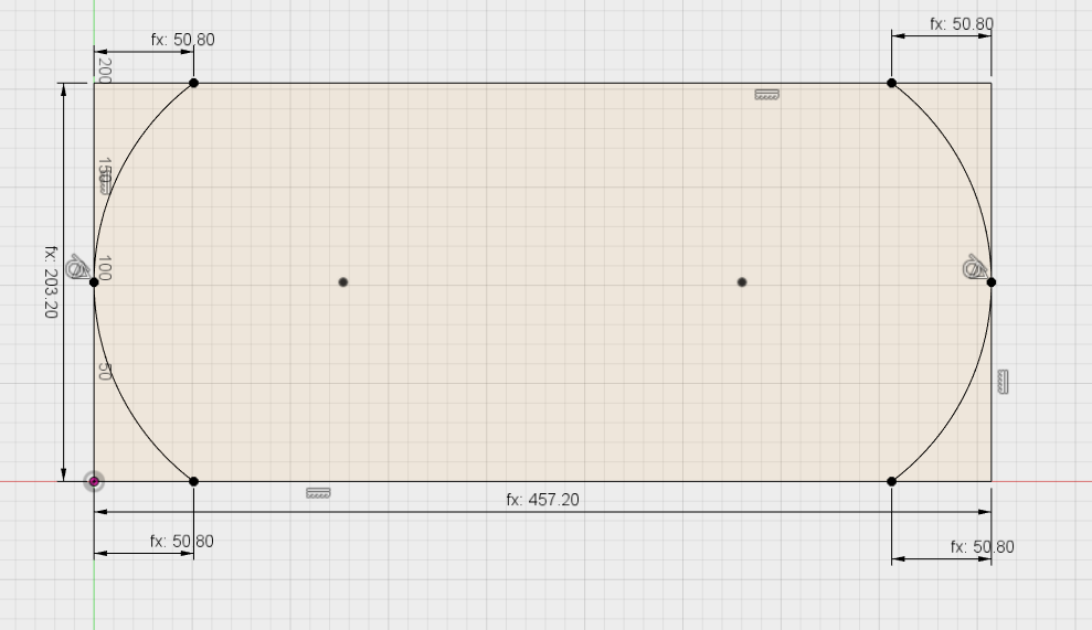
- Extrude the sketch - thickness doesn’t really matter for this.
- Make a new sketch of the top of the extruded body.
- If you want a line to be carved inside the sign, add it now. The offset tool works great for this.
- Save the sketch as DXF.
Add Text in Inkscape
Inkscape has much better tools for adding text than Fusion 360, and also easily exports SVG files which we will need for the gcode generation.
- Open the DXF in Inkscape - when importing, choose manual sizing and make sure it’s set to 1.
- Go to File -> Document Properties -> Resize page to drawing
- Add text. Make each line a separate text box so they can easily be sized differently.
- Set the font and size.
- Align the text where you want it.
- Add some frilly decorative flourishes - search you tube for “inkscape swirl flourish” for some ideas and tutorials
- Save the file as an Inkscape. This file will be the one you can come back and edit if you need to.
- Choose all the text, then go to Path -> Object to Path. After this the text will no longer be editable.
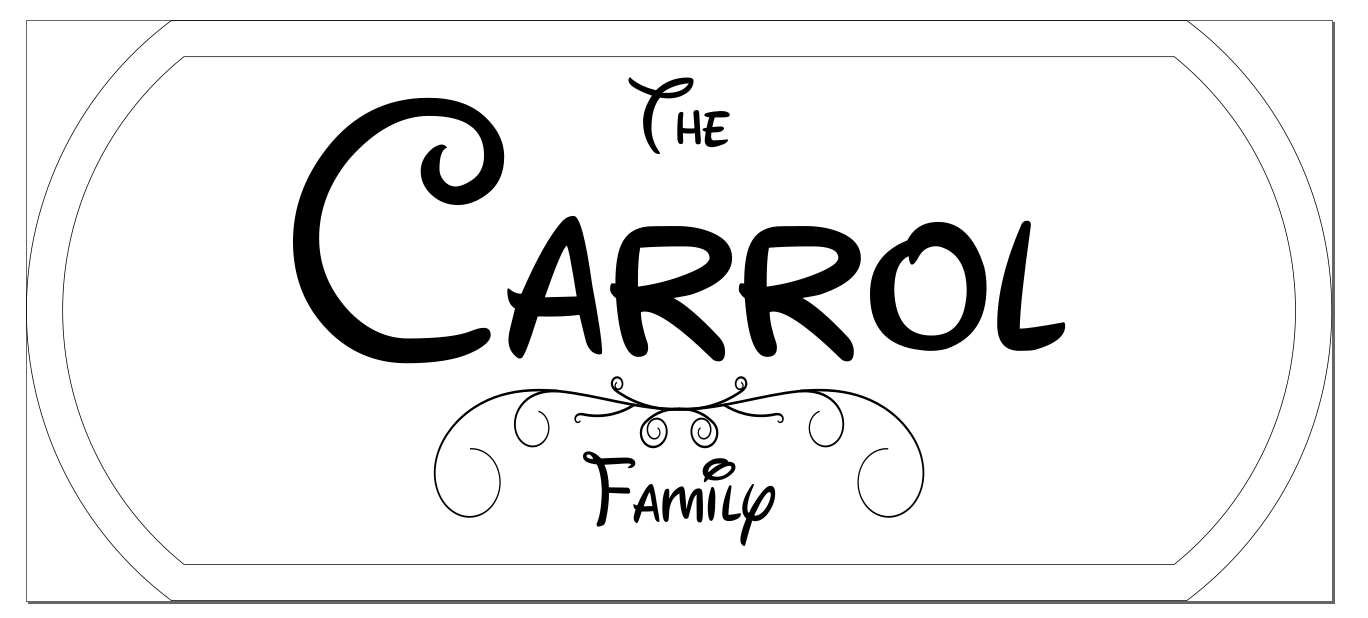
- Save as SVG with a different filename. This is the file we’ll use for machining.
It should look something like this:
Machining
Machinging will be done in this order:
- V-Carving - done first while the wood is nice and secure
- Outside cutting - with tabs to make sure the sign doesn’t move after being cut out
- Laser etching - done last since it doesn’t need to touch the wood so the tabs won’t break
Prepare the Wood
I’ve used both solid pieces of wood and strips I’ve cut on a table saw and glued together. Depends on what you have on hand and the look you are going for. So far I’ve only used cheap SFP 1x6 and solid pine boards. Plane (if needed) and sand the wood fairly smooth to start with. Decide how big your sign is going to be. Be sure to leave some room on the outside for clamps or screws.
Screw or clamp the wood to the machine bed. If using screws, it is essential you predrill the holes since they will be near the edges of the wood and very likely to crack.
If possible, countersink the screws so there’s no chance of the bit hitting them when it’s moving over the wood.
Load LaserWeb and Set Work Coordinates
- Load the V carve bit into the router
- Go to the LaserWeb interface
- Make sure it is set to use the MPCNC Milling Profile
- Load the SVG into LaserWeb
- Click the top element of the SVG and position it at 0,0
- Compare the size to the document properties size in inkscape (in mm). If it is wrong, it’s using the wrong DPI. Inkscape 0.92 and newer uses 96 dpi. You have have to force the DPI in LaserWeb under Settings -> File Settings
- Home the machine (make sure bit is raised well above the wood first)
- Jog to the bottom left corner of where you want to cut
- Slowly jog Z down until you can just barely slide a piece of paper under the bit
- Click Set Zero
- Raise Z back up at least 10mm
- Drag the outline line of the SVG into the gcode area and choose the mill outside cut profile (you aren’t actually going to run this, it’s just to see where it will cut)
- Click Generate Gcode
- Go to control tab and click check size.
- Adjust home position until you are happy with the cutout area.
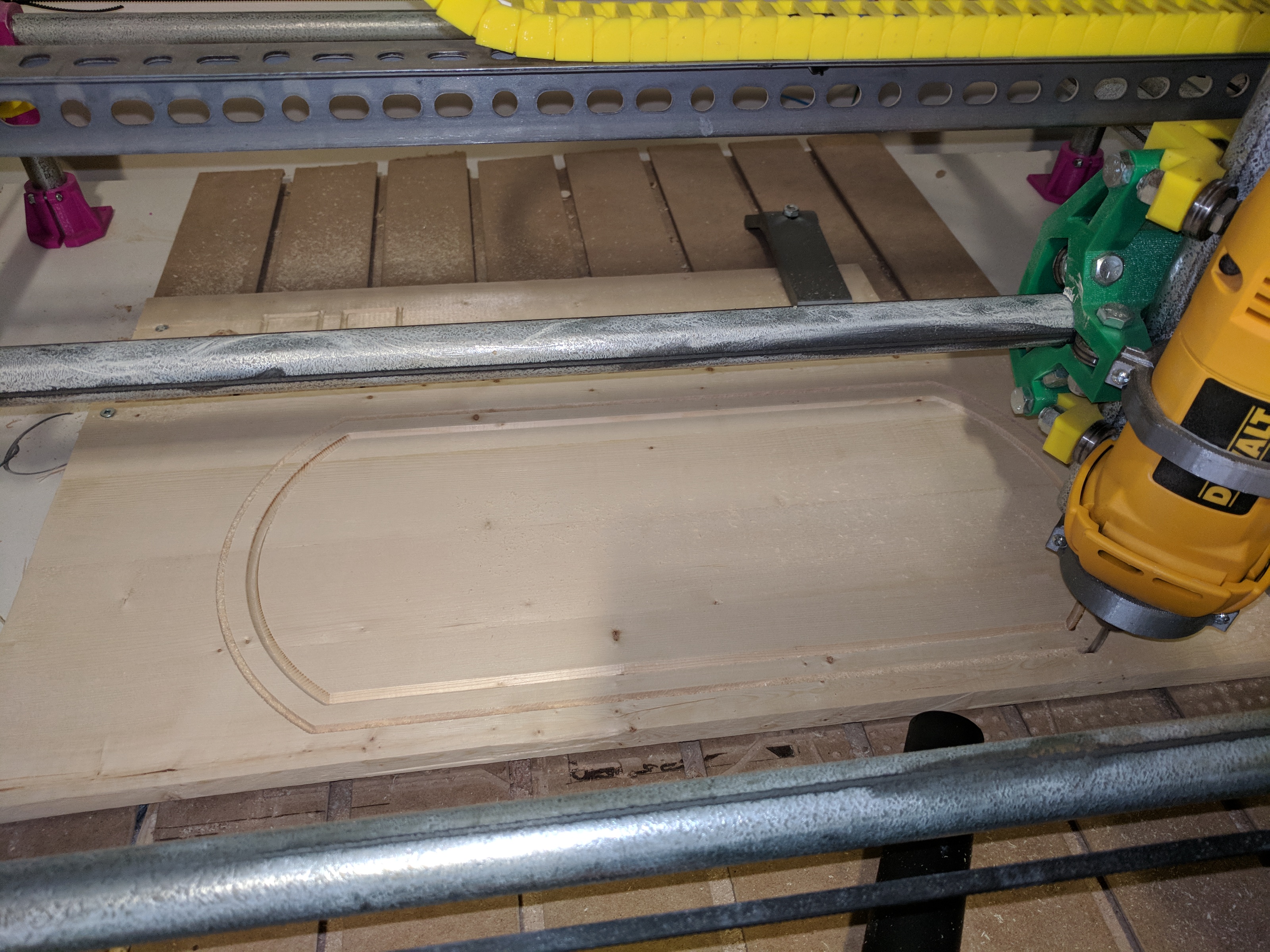
V Carve Line
- Clear the work list in LaserWeb
- Click on the V carve line
- Expand the SVG and drag the path that was selected under documents to the gcode area
- Choose Mill Cut (Not V Carve, that’s for doing the inside of the entire shape)
- Use these settings: (of course, some of these, especially speeds, depend on what wood you are using)
- Rapid Z = 10mm - this is the height above the work piece to travel
- Start Z = 0
- End Z = -5
- Passe Depth = 5
- Plunge Rate = 2
- Cut Rate = 10
- Click Generate Gcode
- Go to control tab
- Run the job
Once that’s finished, vacuum the dust away and switch to the straight cutting tool.
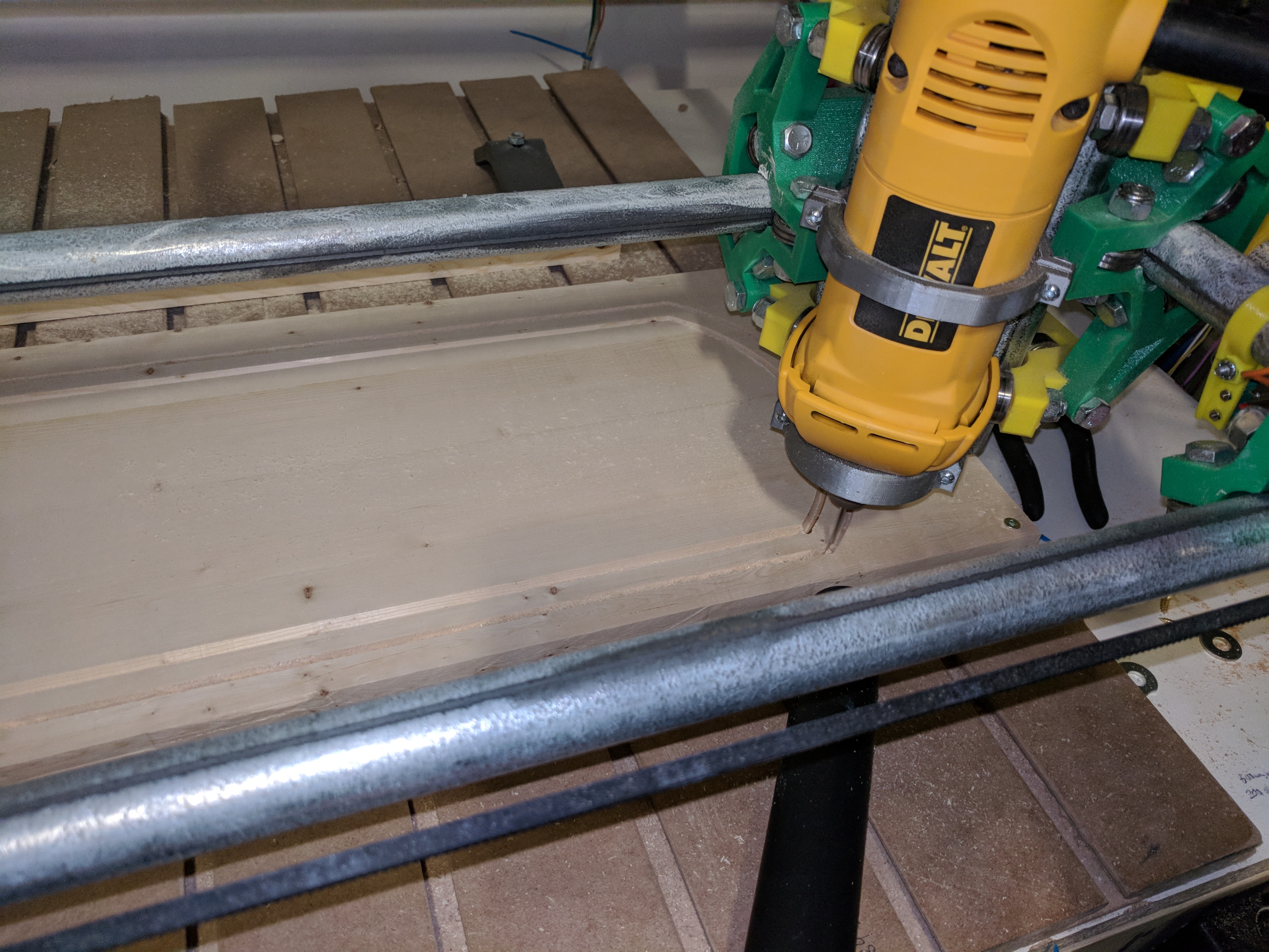
Cutting the Outside
- Remove the existing job
- Choose the outside line, drag to the gcode area
- Set it to Mill Cut Outside
- Use these settings:
- Rapid Z = 10mm
- Start Z = 0
- End Z = -19 (adjust to however thick your wood is)
- Pass Depth = 5
- Tool Diameter = 3.175
- Plunge Rate = 2
- Cut Rate = 10
- Add holding tabs - the dxf file linked at the top contains 4 rectangles that can be resized and moved around to put them in easy to sand locations that will hold the cut sign in place. You can add the same document multiple times if you think you need more tabs.
- Add those shapes to the tabs area at the bottom
- Set the tab depth. The depth is how deep to cut, not how much to leave. Set to about half the thickness of the wood.
- Click Generate Gcode
- Look at the Gcode and make sure your holding tabs are there, and look thick enough to hold the piece in place
- Go to control tab
- Lift Z axis, rehome the machine to make sure you didn’t pull it out of place while switching tools
- Jog to X0 Y0
- Move Z down until bit is at the top of the wood, and click Set Zero
- Lift Z 10mm
- Check the outline, make sure it’s where you expect
- Run job
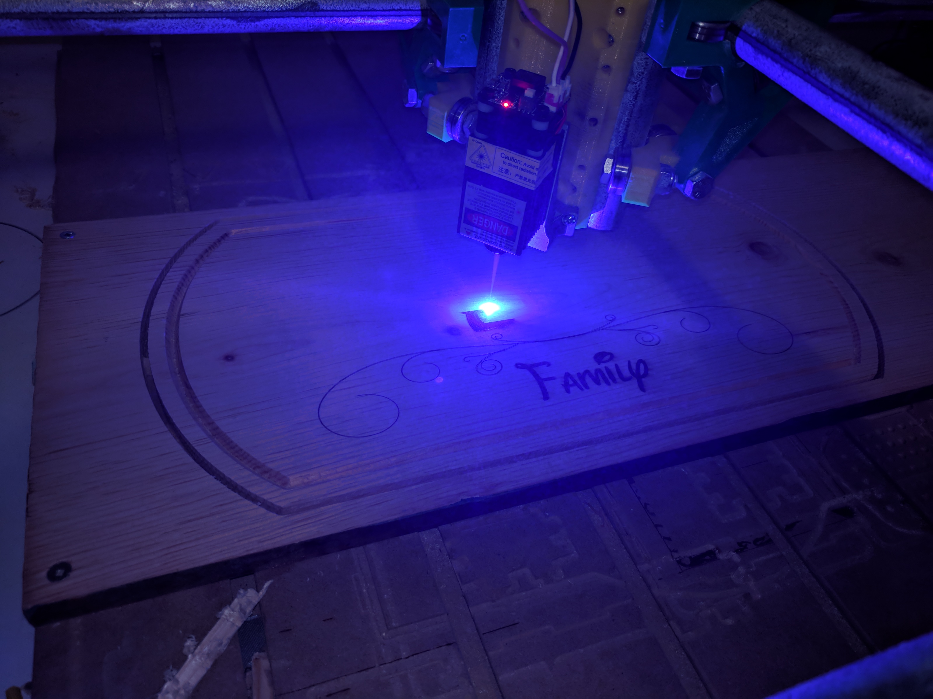
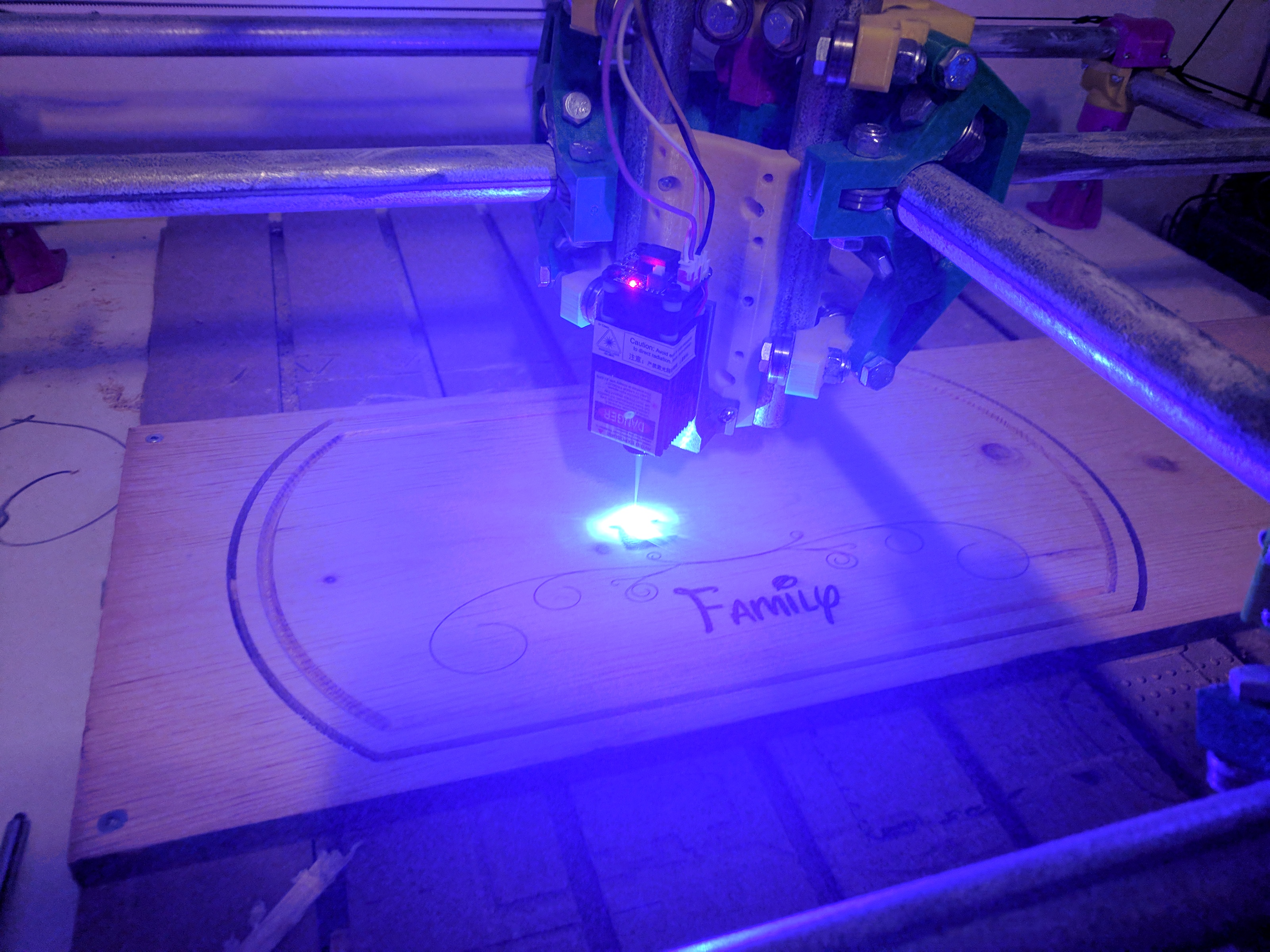
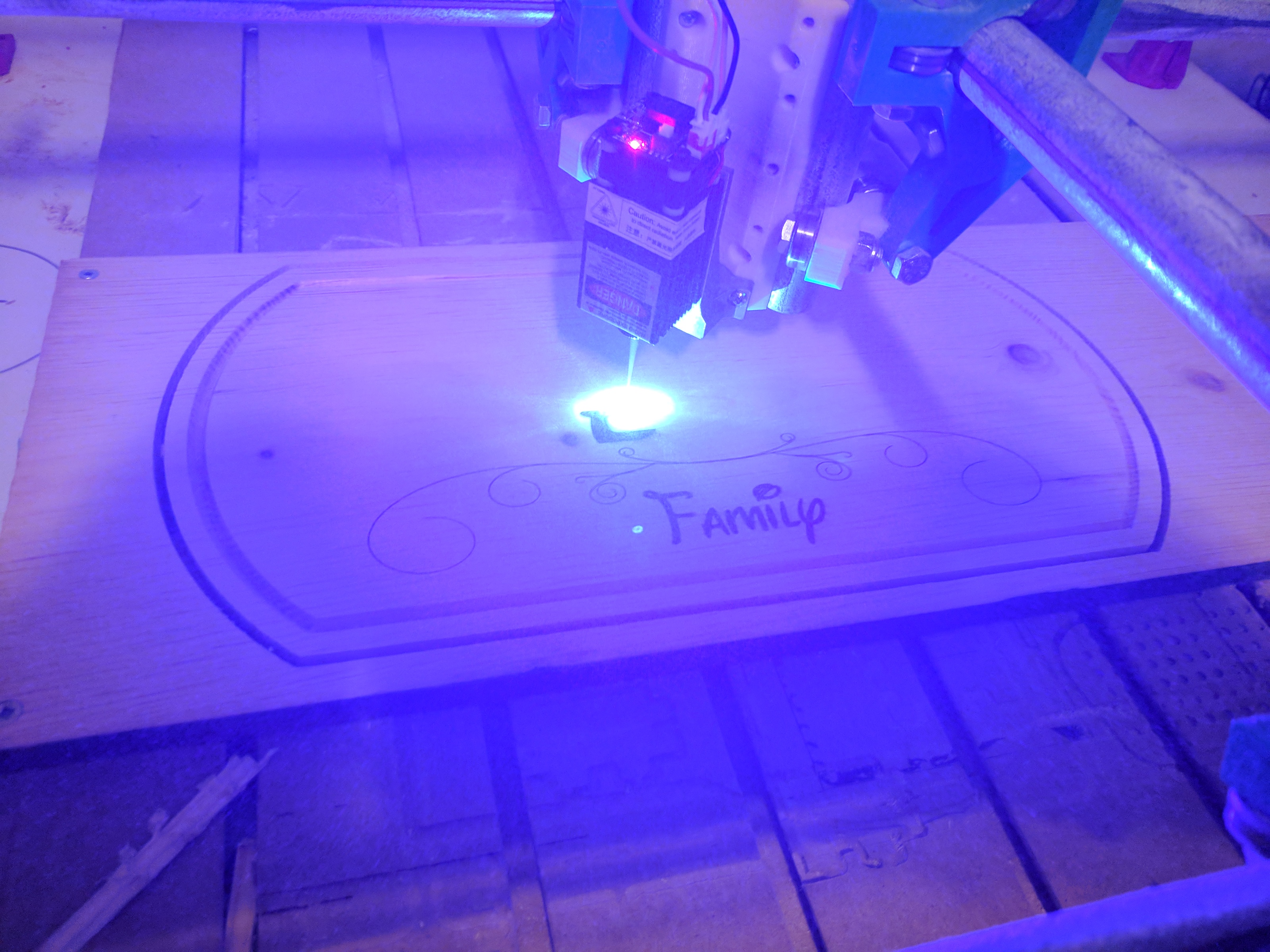
Laser Etching
- Turn the machine off. It will remember your work offsets so you’ll be able to go back to the right place easily.
- Vacuum and dust the top surface of the sign thoroughly.
- Remove the router, install the laser and hook up the power and control wires.
- Put on your laser safety glasses.
- Turn the machine back on and home it.
- Switch to the MPCNC Laser Profile - it has different start gcode that enables laser mode
- Home the machine
- Go to X0 Y0
- Jog to X -1.7, Y +0.8 - this compensates for the slight offset between the tools. You’ll have to find your own measurements for this.
- Lower the tool until it just touches the workpiece
- Set Zero
- Click the Focus Laser macro (raises laser to 38mm, the focus height I have it calibrated for)
- Click Test laser, make sure it’s working and focused. Click again to turn off.
- Select all the text and add them to the gcode section. Choose the laser fill path profile for your wood (this is a preset I’ve created).
- Select the flourishes, choose laser outline profile
- Generate Gcode
- Run the job
Finishing
- Turn off the machine
- Unscrew the wood
- Cut the tabs with a hacksaw blade, and sand them off with belt sander
- Sand the v grooves and outside with sandpaper or a sanding sponge
- Stain, poly, or laquer the wood. Be careful to brush gently around the lasered parts so you don’t disturb the blackened parts
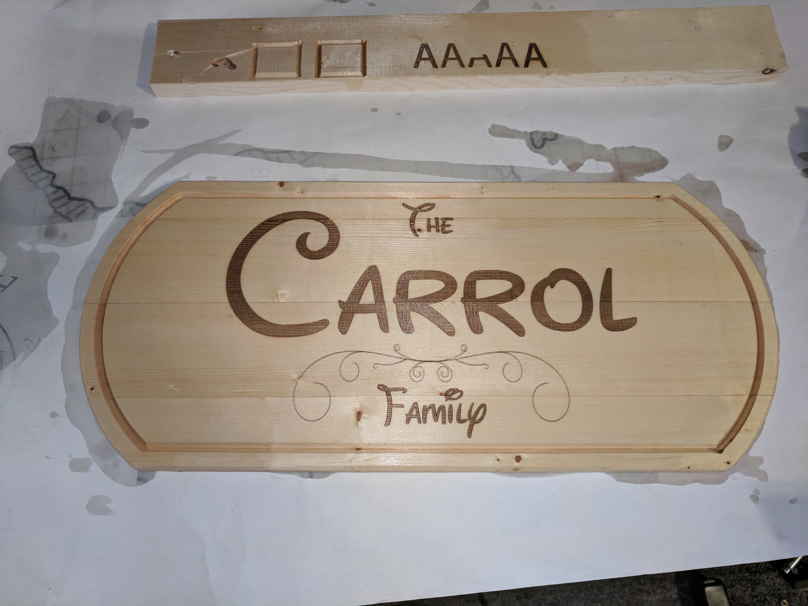
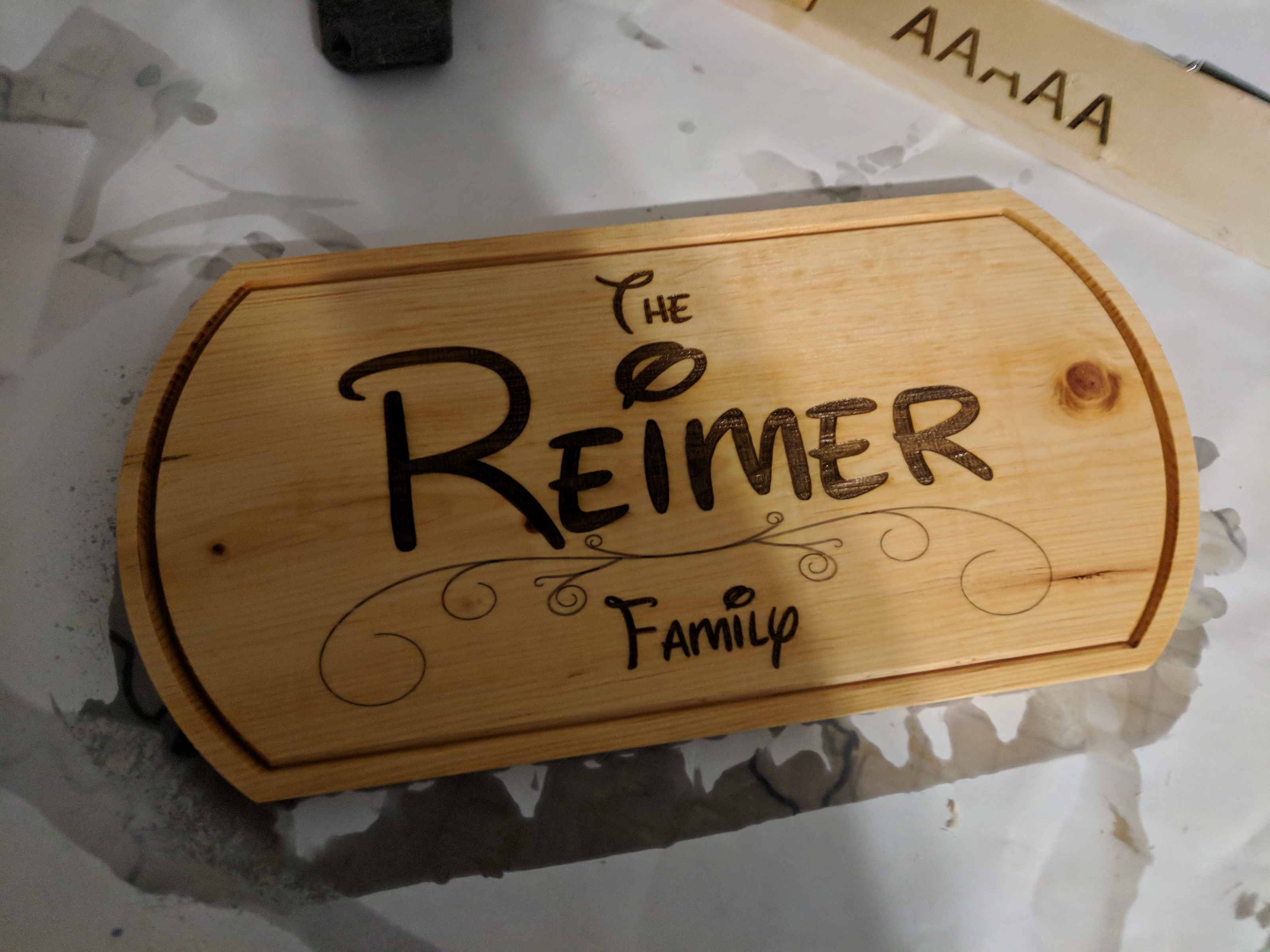
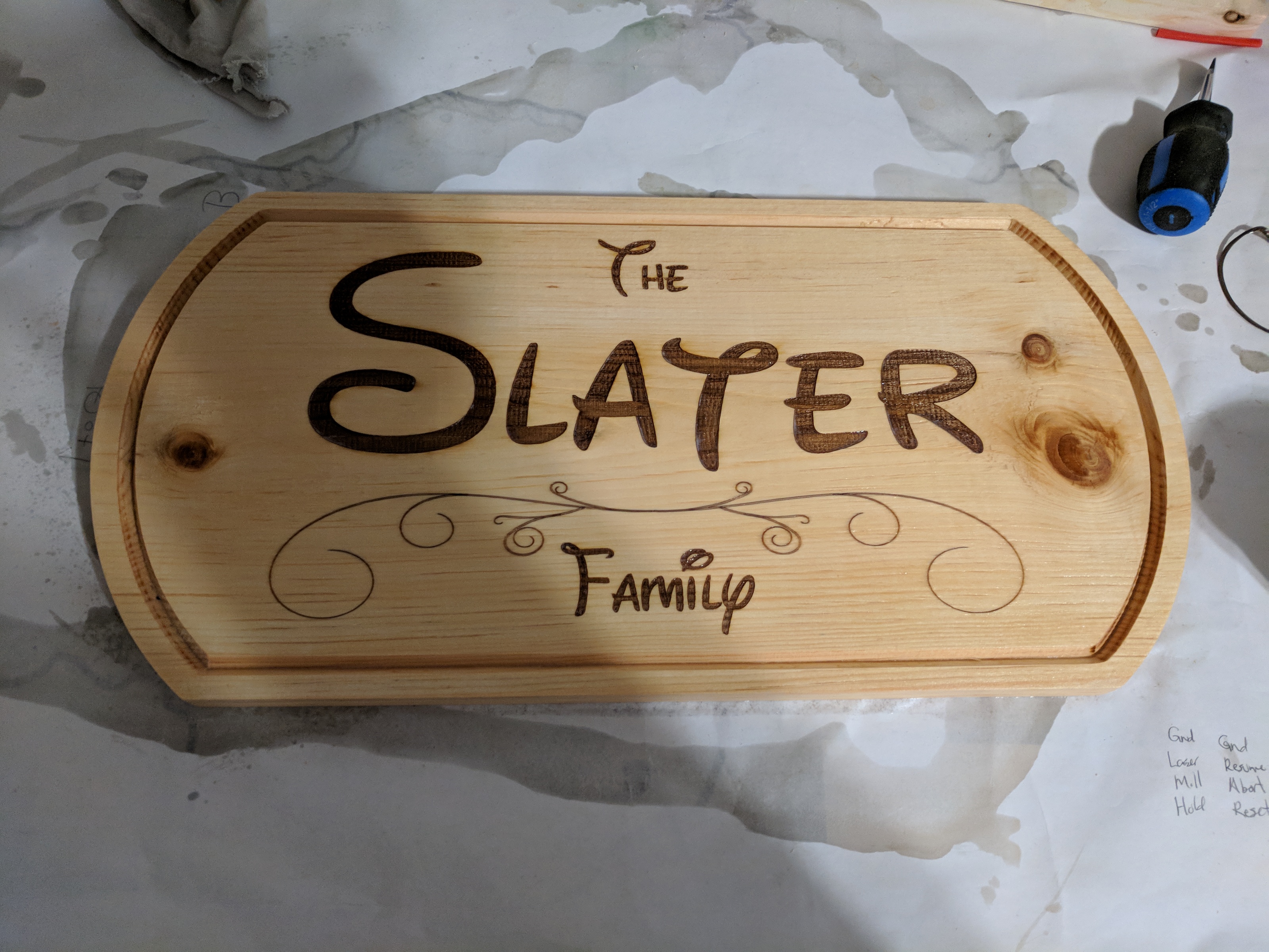
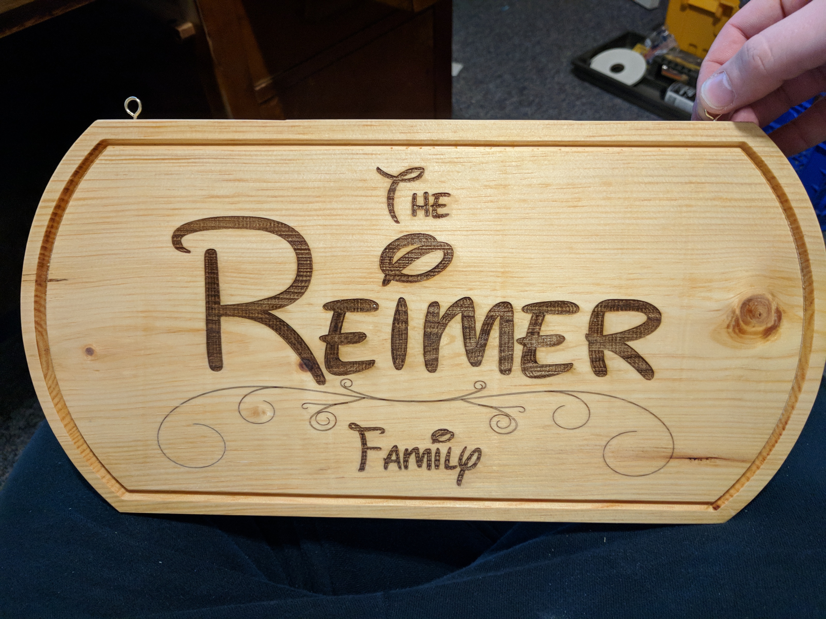
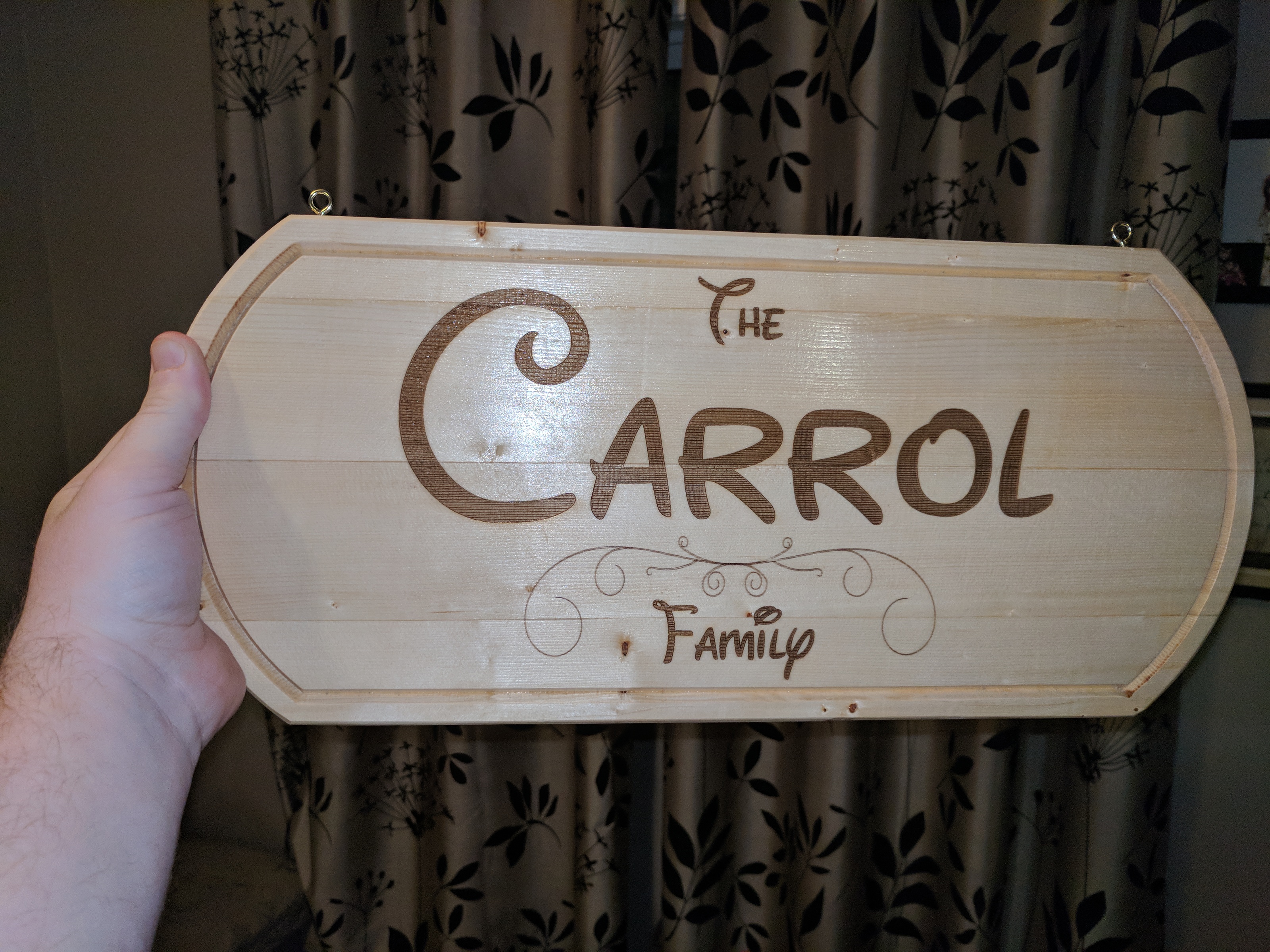
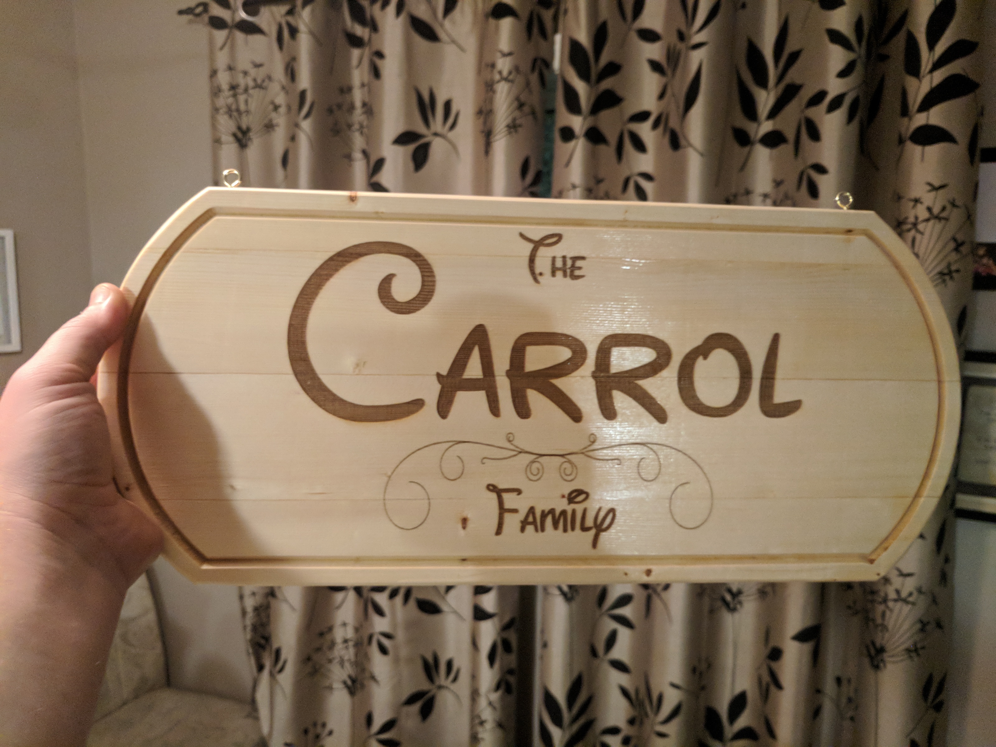
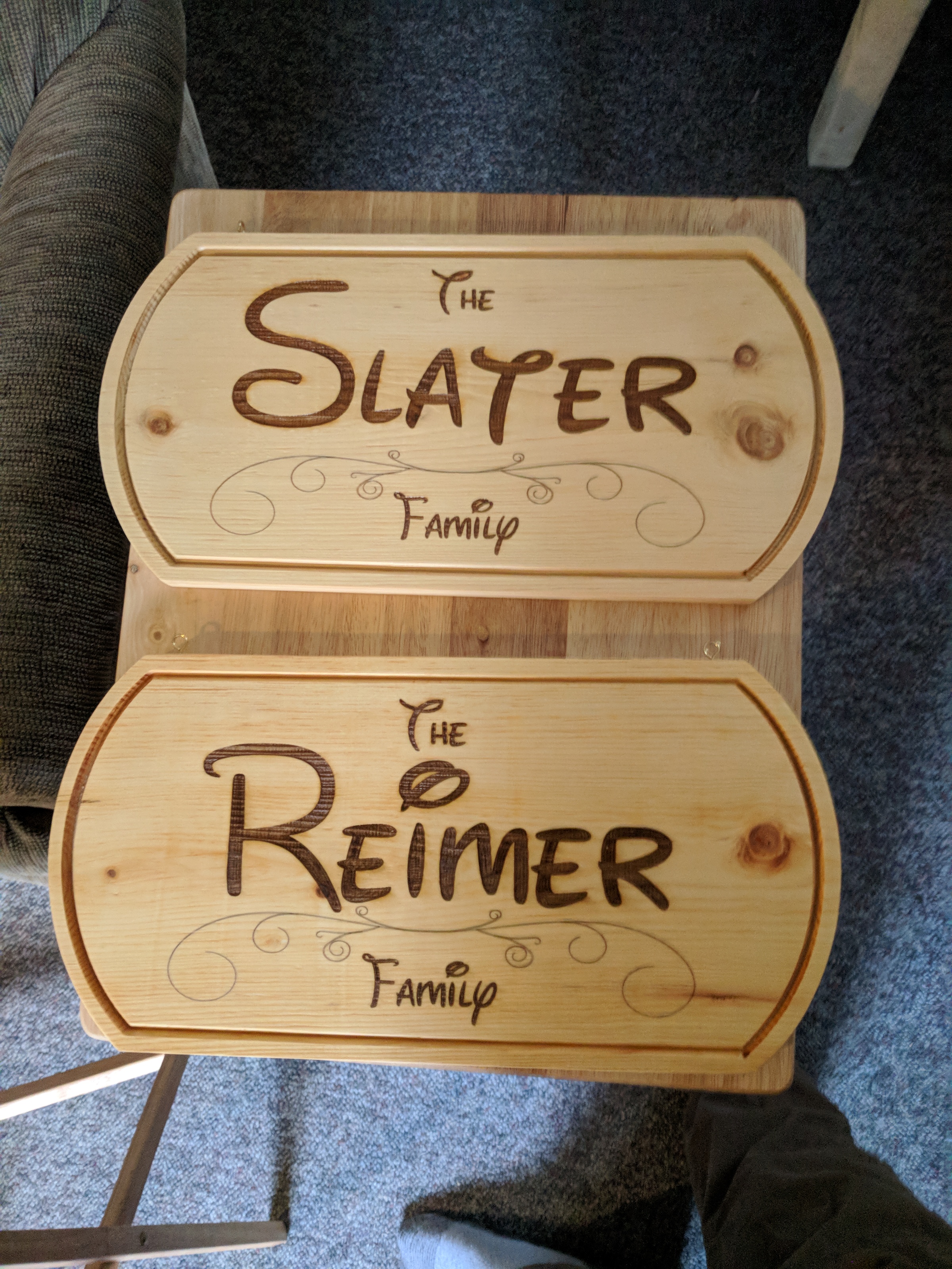
Results
Here are a few of the signs I’ve created using this and similar techniques: